
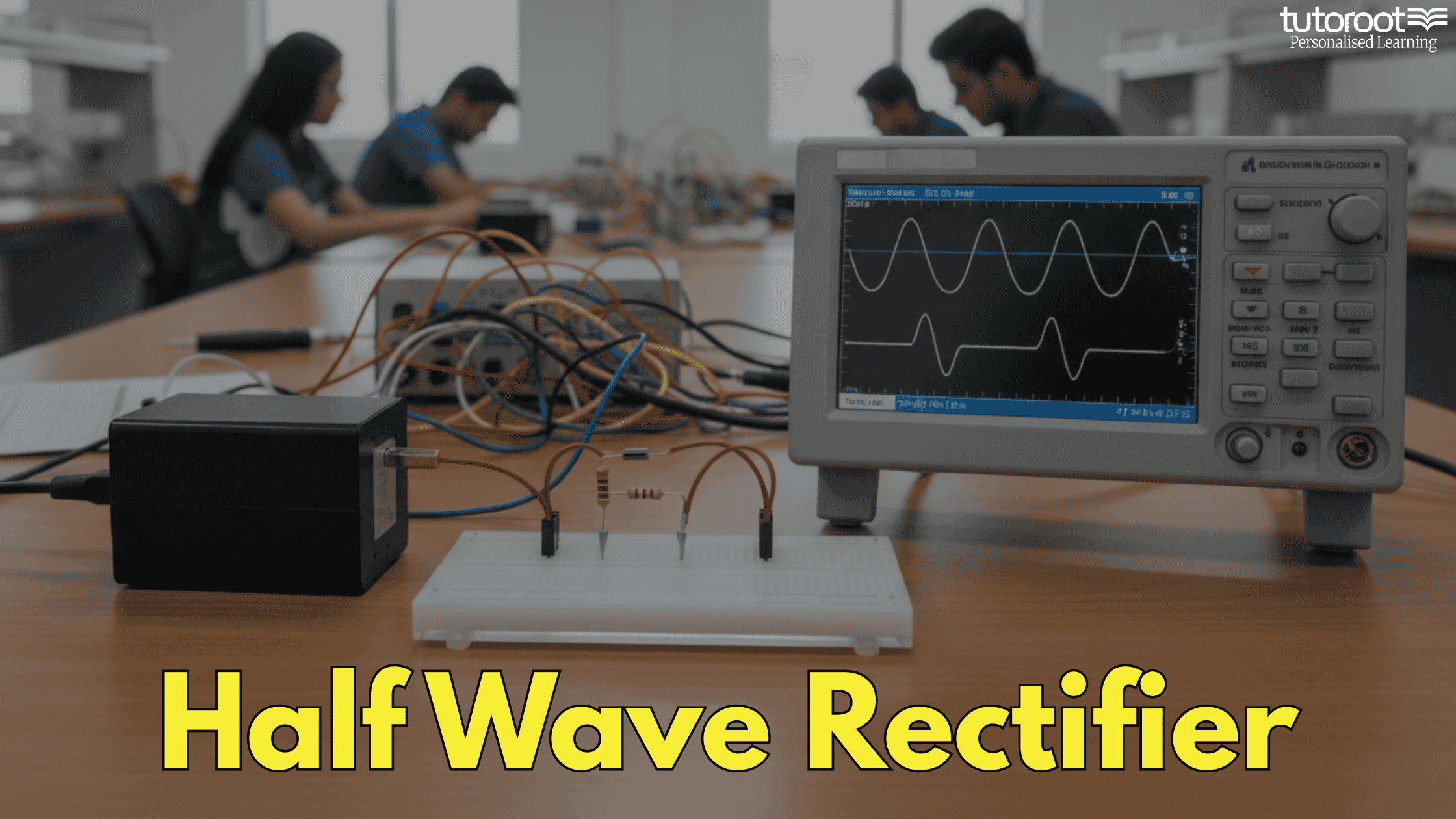
Working of Half Wave Rectifier
The Half Wave Rectifier is a fundamental component in electronic circuits, primarily used to convert Alternating Current (AC) into Direct Current (DC). For students and hobbyists, mastering this topic is the first step toward understanding power supply design.
In this guide, we break down the working principle, the role of diodes, and the mathematical formulas that govern half-wave rectification.
What is a Half Wave Rectifier?
A Half Wave Rectifier is the simplest form of a rectifier. It uses a single diode to convert AC voltage into a pulsating DC voltage. Unlike full-wave rectifiers, this device only allows one-half of the AC cycle (either positive or negative) to pass through, effectively blocking the other half.
Key Components
A standard HWR circuit consists of three primary elements:
Transformer: Usually a step-down transformer to reduce the high input AC voltage.
Diode: The “gatekeeper” that allows current to flow in only one direction.
Resistive Load ($R_L$): The component where the converted DC output is obtained
How a Half Wave Rectifier Works
The transformation from AC to DC happens in two distinct stages based on the input waveform.
1. The Positive Half Cycle
When the positive half of the AC signal reaches the diode, the diode becomes Forward Biased. In this state, the diode acts like a closed switch, allowing current to flow through the load resistor ($R_L$).
2. The Negative Half Cycle
When the AC signal switches to the negative half, the diode becomes Reverse Biased. It now acts like an open switch, blocking the flow of current. Consequently, the output voltage drops to zero during this period.
The Result: The output is a series of “humps”—a pulsating DC signal that only represents the positive portions of the original AC wave.
Essential Half Wave Rectifier Formulas
To calculate the efficiency and performance of the circuit, we use the following standard equations:
-
RMS Value of Current:
$$I_{rms} = \frac{I_m}{2}$$ -
Average (DC) Voltage:
$$V_{dc} = \frac{V_m}{\pi}$$ -
Ripple Factor ($\gamma$):
This measures the “purity” of the DC output. For a half-wave rectifier, it is typically 1.21.
$$\gamma = \sqrt{ \left(\frac{V_{rms}}{V_{dc}}\right)^2 – 1 }$$ -
Efficiency ($\eta$):
The maximum theoretical efficiency of a half-wave rectifier is 40.6%.
$$\eta = \frac{P_{dc}}{P_{ac}}$$
Improving Output: The Capacitor Filter
In practical applications, a “pulsating” DC is rarely useful because most electronics require a steady, constant voltage. This is where a Capacitor Filter comes in.
Why use a filter?
A capacitor is connected in parallel with the load resistor.
Charging: When the rectifier output rises, the capacitor charges to the peak voltage.
Discharging: When the rectifier output falls, the capacitor releases its stored energy into the load.
This “fills in the gaps” between the pulses, significantly reducing the Ripple Factor and creating a smoother DC output.
Advantages and Disadvantages
| Pros | Cons |
| Simple design with very few components. | Low output voltage and power. |
| Extremely cost-effective. | High power loss (low efficiency). |
| Ideal for low-power signal demodulation. | High ripple content requiring heavy filtering. |

Frequently Asked Questions (FAQs)
1. Why is the ripple factor so high in a half-wave rectifier?
Because the circuit stays “off” for half of the entire cycle, the output fluctuates significantly between the peak voltage and zero, leading to a high ripple factor of 1.21.
2. Can a half-wave rectifier be used for high-power applications?
Generally, no. Due to its low efficiency (40.6%) and high power loss, it is mostly used for low-power signal processing or battery charging rather than heavy-duty power supplies.
3. What is the Peak Inverse Voltage (PIV)?
The PIV is the maximum voltage the diode must withstand when it is reverse-biased. For a half-wave rectifier, $PIV = V_m$.