
Difference Between Series and Parallel Circuits
In order to find out how various quantities such as current, voltage, and resistance act in circuits, it is important to find out the various differences between Series and Parallel Circuits. Moreover, based on the number and type of devices connected to each other, different types of circuits are employed. And here in this below article, we will help you understand the difference between series and parallel circuits, by providing a detailed description of parallel circuits, and series circuits, along with their circuit diagrams.
What is a Series Circuit?
If the current flow in a circuit passes through all the components involved in the said circuit, then it is called Series Circuit. And moreover, in this type of circuit, the current flow follows a single path or direction. For instance, if you consider house decorating lights, then you could observe that they are simply multiply connected in series. However, there is a big disadvantage in these types of circuits, if one piece of electrical equipment connected to the circuit fails, all other equipment also does not work.
Series Circuit Diagram

Advantages of series circuits
- As shown in the series connection diagram, it features a straightforward design that is simple to grasp.
- It does not easily overheat.
- It has a larger output voltage, allowing us to connect more powerful appliances.
- The current is constant throughout the circuit.
Disadvantages of a series circuit
- Circuit resistance increases as the total number of components in the circuit grow.
- If a defect develops at any point in the circuit, the entire circuit will fail.
What is a Parallel Circuit?
Contrary to the Series Circuit, this involves multiple paths embedded in a circuit, which carry current to the different electrical equipment connected to them. However, one thing you should remember, even though they are multiple different paths for current to flow, the voltage will remain constant throughout the circuit.
Parallel Circuit Diagram

Advantages of parallel circuits
- As shown in the above parallel circuit diagram, in a parallel circuit connection, if one component fails, the current does not cease and continues to flow through the other components, allowing the remaining connection to function efficiently.
- Because the voltage across each component in a parallel circuit is the same, all components perform efficiently.
- A parallel circuit allows you to simply connect or disconnect a new component without interfering with the operation of another component.
Disadvantages of parallel circuit
- An additional voltage source cannot be used in a parallel circuit connection.
- A parallel circuit connection needs a large number of wires for connecting.
Circuit Diagrams of Series and Parallel Connections
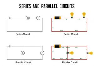
From the above diagrams, you can see that the current flow in the series circuit follows a singular path, while the current in the parallel circuit follows multiple paths.
Difference Between Series Circuit and Parallel Circuit
There are multiple differences between Series and Parallel Circuits, which we are going to talk about briefly below.
| Parameters | Series | Parallel |
| Current Flow | Current Flows follow a single path. | Current Flows follow multiple paths. |
| Components Arrangement | All components are connected in series. | All components are connected in parallel. |
| Voltage | Voltage differs across each resistor in the circuit. | The voltage remains the same. |
| Mathematical Representation | Vt=V1+V2+V3
|
V1=V2=V3
|
| Component Failure | If one component fails, all other components are rendered useless. | Even if one component fails, it does not affect the working of other components in the circuit. |
Conclusion
In the above article, we have covered all about the voltage in parallel and series connections, as well as a comparison between series and parallel circuits or a comparison of series vs parallel circuits. Now, if you find these or other topics difficult to understand, or struggling to solve different types of questions under these chapters. Then we suggest you join the Online interactive classes offered by the Tutoroot platform. So that you can access various amazing features, such as cost-effective prices, doubt-clearing sessions, best study materials, and many more.
Frequently Asked Questions
What is a series circuit?
As explained in the above section, it is a circuit where the current is along a single path, and all the components are connected in series.
How do you calculate total resistance in a series-parallel circuit?
In order to find the total resistance in a parallel circuit, the below-mentioned formula must be used.
1/RT = 1/RT1 + 1/RT2 + 1/RT3
2 thoughts on “Difference Between Series and Parallel Circuits”