
What is Bridge Rectifier? Circuit Diagram, Working

Introduction to Bridge Rectifier
A bridge rectifier is an electrical circuit that converts alternating current (AC) into direct current (DC).
Rectifiers are widely explained in standard electronics textbooks and academic references.
Therefore, rectifiers are widely used in power supplies to run electronic equipment. Among different rectifiers, this type of rectifier is the most effective and belongs to the full-wave rectifier category.
This article explains the working of this rectifier circuit, along with its circuit diagram, waveform, and key characteristics.
So, Rectifiers are classified based on their operation:
Types of Rectifiers
- Half-wave rectifier
- Full-wave rectifier
A full-wave rectifier converts both the positive and negative half cycles of an AC signal into a pulsating DC output.
As a result, it is more efficient than a half-wave rectifier.
Full-wave rectifiers are in turn classified into two types:
- Bridge rectifier
- Centre-tapped full-wave rectifier
Let us know more about full-wave bridge rectifiers before we attempt to get deeper into learning about bridge rectifiers.
A full wave rectifier is a rectifier that transforms both halves of each alternating wave cycle (alternating current) into a pulsing DC (direct current) signal.
Full-wave rectifiers are used for a smoother and more consistent supply of power. Full-wave rectifiers are used to convert a whole cycle of alternating current voltage (AC) to direct current voltage (DC).
The differentiation between these two types of full-wave rectifiers goes a long way in understanding effectively the full-wave rectifier working
A centre-tapped full-wave rectifier uses a centre-tapped transformer, two diodes, and a resistive load.
In contrast, this rectifier circuit uses four diodes arranged in a bridge configuration and does not require a centre-tapped transformer.
What is a Bridge Rectifier?
A bridge rectifier is a full-wave rectifier that uses four diodes to create a close-loop bridge. The diodes operate in pairs during each positive and negative half cycle, resulting in no power waste.
A bridge rectifier does not require a center tap over the transformer’s secondary winding. The input is sent through a transformer to the diode bridge’s diagonal. Unlike the center tap rectifier, which consumes 50% of the transformer, the transformer in this circuit is constantly busy since it delivers power during both cycles of input AC.
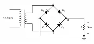
Circuit Diagram
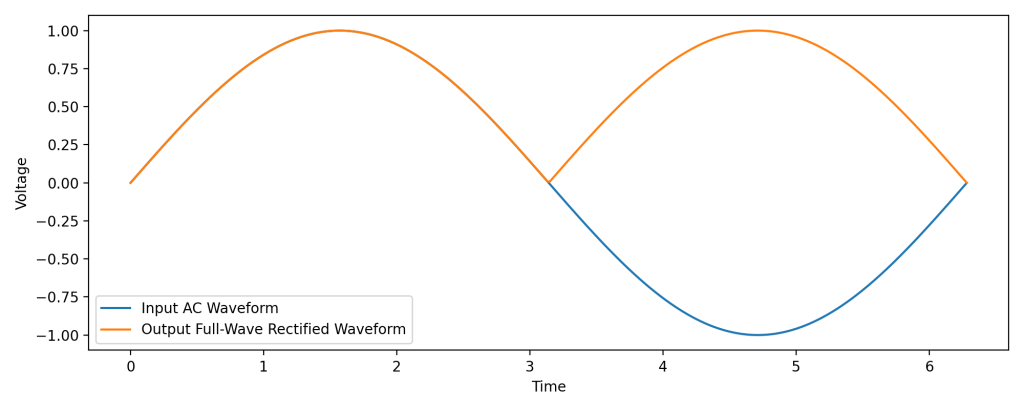
Output Waveform
Working Principle
Typically, this circuit works as follows:
Step 1: Positive half cycle
Terminal A becomes positive and terminal B becomes negative. Diodes D1 and D3 conduct, while D2 and D4 remain reverse-biased.
Step 2: Negative half cycle
Terminal B becomes positive and terminal A becomes negative. Diodes D2 and D4 conduct, while D1 and D3 remain reverse-biased.
Thus, this full-wave rectifier enables the flow of the electric current during positive as well as negative half cycles of the input AC signal.
Formulae and Characteristics
Let us understand the characteristics of a bridge rectifier based on the following aspects:
Ripple Factor
Definition:
Ripple factor measures the smoothness of the DC output signal.
The ripple factor mathematically is defined as the ratio of ripple voltage to pure DC voltage.
Formula:
\(\gamma = \sqrt{ (\frac{ V_{rms} }{ V_{dc} }) ^{2}-1}\)
Value:
The ripple factor of a bridge rectifier is 0.48.
Peak Inverse Voltage
A peak inverse voltage is the greatest voltage that a diode can endure when biased in reverse. The diodes D1 and D3 are conducted during the positive half cycle, whereas D2 and D4 are not.
Similarly, during the negative half cycle, diodes D2 and D4 current whereas diodes D1 and D3 do not.
Efficiency
The efficiency of a rectifier influences how well it converts Alternating Current (AC) into Direct Current (DC). A bridge rectifier’s highest efficiency is 81.2%.
\(\eta = \frac{DC Output Power}{AC Output Power}\)
Pros and Cons of Bridge Rectifier
Advantages of Full Wave Bridge Rectifier
- The efficiency of a bridge rectifier is greater than that of a half-wave rectifier. The rectifier efficiency of the bridge rectifier and the center-tapped full-wave rectifier, on the other hand, is the same.
- The bridge rectifier’s DC output signal is smoother than the DC output signal of a half-wave rectifier.
- A half-wave rectifier uses just half of the incoming AC signal and blocks the other half. A half-wave rectifier wastes half of the input signal. A bridge rectifier lets electricity flow through both the positive and negative halves. As a result, the output DC signal is almost equivalent to the input AC signal.
Disadvantages of Bridge Rectifier
- A bridge rectifier’s circuit is more complicated than that of a half-wave rectifier or a centre-tapped full-wave rectifier. Bridge rectifiers require four diodes, whereas half-wave and center-tapped full-wave rectifiers need just two.
- As more diodes are utilized, more power is lost. Only one diode is conducted during each half cycle of a center-tapped full-wave rectifier. With a bridge rectifier, on the other hand, two diodes linked in series conduct throughout each half cycle. As a result, the voltage drop is larger with a bridge rectifier.
Final Notes
Tutoroot offers one -to-one online tuition classes to help you learn more about Bridge Rectifier. Our expert faculty are IITs and from coveted Universities who can help you in your learning journey. Enroll in our Physics online tuition for the best subject knowledge and try with a FREE DEMO Session

FAQ’s
Q1. What is the ripple factor of a bridge rectifier?
0.48
Q2. What is the RMS value of the Bridge Rectifier?
RMS Voltage =
Q3. How does a bridge rectifier work?
When an AC signal is applied, terminal A becomes positive and terminal B becomes negative during the positive half cycle. As a result, diodes D1 and D3 become forward-biased, while diodes D2 and D4 remain reverse-biased.
During the negative half cycle, terminal B becomes positive and terminal A becomes negative. This causes diodes D2 and D4 to become forward-biased, while diodes D1 and D3 remain reverse-biased.
Thus, a bridge rectifier allows current to flow during both half cycles of the AC input.
Q4. Does the bridge rectifier convert AC to DC?
Yes, a bridge rectifier is primarily used to convert AC voltage into DC voltage.
Q5. Why is a bridge rectifier commonly used?
A bridge rectifier is commonly used because it converts both halves of the AC cycle into DC, resulting in higher efficiency and a smoother output.