
What is Thevenin Theorem? – Deriving Thevenin Theorem Formula
Thevenin’s Theorem is a fundamental concept in electrical engineering that simplifies complex circuits into easier-to-understand equivalents. Understanding this theorem is crucial for circuit analysis and design. Let’s delve into the details of Thevenin’s Theorem, including its derivation and practical applications.
What is Thevenin’s Theorem?
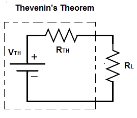
Thevenin’s Theorem states that any linear electrical network can be replaced by an equivalent circuit consisting of a single voltage source in series with a resistor. This equivalent circuit accurately models the original network’s behavior as seen from a specific pair of terminals.
Explaining Thevenin’s Theorem
In essence, Thevenin’s Theorem allows us to simplify complex circuits by finding an equivalent Thevenin voltage and Thevenin resistance. This makes circuit analysis more manageable and enables us to predict how the circuit will respond to different loads.
Imagine you have a complex electrical circuit with multiple components like resistors, voltage sources, and current sources. Thevenin’s Theorem allows you to condense this complexity into a simpler representation of a Thevenin equivalent circuit while preserving the original circuit’s behavior between two terminals.
To apply Thevenin’s Theorem, follow these steps:
- Identify the terminals: Determine the two terminals (let’s call them A and B) across which you want to simplify the circuit.
- Calculate Thevenin Voltage (V_th): Disconnect the load connected across A and B. Calculate the open-circuit voltage (V_th) across terminals A and B.
- Calculate Thevenin Resistance (R_th): Turn off all independent sources (voltage and current sources) and calculate the equivalent resistance looking back into the circuit from terminals A and B.
Thevenin’s Theorem Statement and Proof
The statement of Thevenin’s Theorem can be summarized as follows:
The formal statement of Thevenin’s Theorem is as follows: “Any linear electrical network containing independent and dependent sources can be replaced by an equivalent circuit consisting of a single voltage source (Vth) in series with a single resistor (Rth). This equivalent circuit is valid only at the terminals of interest.
Thevenin’s Theorem Formula
The Thevenin voltage VTh is the open circuit voltage at the terminals of interest, and the Thevenin resistance RTh is the equivalent resistance looking into those terminals. The formula is given by:
Vth = Voc
Rth = Voc/Isc
Here, Vth represents the Thevenin voltage, Rth denotes the Thevenin resistance, Voc is the open-circuit voltage, and Isc is the short-circuit current.
Thevenin’s Theorem Derivation
To derive the Thevenin equivalent circuit, we start by removing all sources in the original circuit and determining the voltage across the terminals of interest. Then, the circuit is simplified to find the Thevenin resistance. This step-by-step process results in the derivation of the Thevenin voltage and resistance.
To derive Thevenin’s Theorem formula, we start by considering a complex circuit with multiple elements. By progressively simplifying this circuit, we ultimately arrive at the Thevenin equivalent circuit. The process involves finding the open-circuit voltage and the short-circuit current, which serve as the basis for determining Vth and Rth respectively.
- Finding Open-Circuit Voltage (Voc): We disconnect the load from the original circuit and measure the voltage across its terminals. This voltage is the open-circuit voltage.
- Finding Short-Circuit Current (Isc): We short-circuit the load terminals and measure the current flowing through the circuit. This current is the short-circuit current.
- Calculating Vth:The open-circuit voltage directly translates to Vth as there is no current flowing through the load.
- Calculating Rth: By applying Ohm’s Law (R=V/I ), we divide the open-circuit voltage (Voc) by the short-circuit current (Isc) to obtain Rth
Thevenin’s Theorem Proof
The proof of Thevenin’s Theorem is based on the superposition principle and the linearity of circuits. By analyzing the behavior of the original circuit with different independent sources, we can demonstrate how the Thevenin equivalent circuit accurately represents the network.
Thevenin Theorem Examples
- Example 1: Consider a circuit with a voltage source of 12V and a resistor of 4Ω. By applying Thevenin’s Theorem, we can determine the equivalent voltage and resistance to simplify the analysis.
- Example 2: In a more complex circuit with multiple sources and resistors, Thevenin’s Theorem offers a straightforward way to predict the circuit’s behavior under different conditions.
Limitations of Thevenin Theorem
While Thevenin’s Theorem is a powerful tool for circuit analysis, the following are a few limitations,
- Applicable only to linear networks (those obeying Ohm’s Law).
- Assumes networks are time-invariant (constant parameters over time).
- Might not be suitable for circuits with non-linear components like diodes or transistors.
Major Applications of Thevenin Theorem
Here are a few major applications of Thevenin’s Theorem,
- Circuit design: Thevenin’s Theorem is used to simplify complex circuits during the design phase.
- Fault analysis: By applying Thevenin’s Theorem, engineers can identify faults and troubleshoot electrical networks more efficiently.
- Simulation and modeling
- System optimization
- Fault diagnosis
Final Notes
Understanding Thevenin’s Theorem is essential for electrical engineering students and professionals alike. By mastering this concept, you can streamline circuit analysis and design processes, making your work more efficient and effective.
This article discusses in-depth Thevenin’s Theorem along with Thevenin’s Theorem examples and Thevenin’s Theorem formula further exploration of related concepts, please visit our blog section. If you seek personalized online tuition, Tutoroot offers exceptional physics online tuition services to address any queries you may have. Book a FREE DEMO session by clicking here.
FAQs
State Thevenin’s Theorem
Thevenin’s Theorem states that any linear electrical network can be replaced by a simpler equivalent circuit consisting of a voltage source (Vth) in series with a resistor (Rth), as viewed from the terminals of interest.
What is Thevenin’s Theorem Formula?
The formula for Thevenin’s equivalent circuit is:
Vth = Voc
Rth = Voc/Isc